
Quarter Wave Transformer Calculator
Introduction
Calculators are indispensable tools for engineers, students, and professionals alike, aiding in various mathematical computations. One such essential tool is the quarter wave transformer calculator, which assists in designing and analyzing transmission lines. In this article, we’ll delve into how to use this calculator effectively, including its formula, an example solve, frequently asked questions, and a conclusion.
How to Use
Using the quarter wave transformer calculator is straightforward. Enter the input parameters such as the characteristic impedance of the transmission line and the desired impedance at the termination. After providing these values, click the “Calculate” button to obtain the results.
Formula
The formula for calculating the length of a quarter wave transformer is:
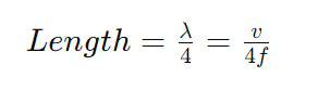
Where:
- Length is the length of the quarter wave transformer.
- λ is the wavelength.
- v is the velocity of propagation of the transmission line.
- f is the frequency.
Example Solve
Let’s consider an example where the characteristic impedance of the transmission line is 50 ohms and the desired impedance at the termination is 75 ohms. Assuming the velocity of propagation is 2×1082×108 meters per second and the frequency is 1 GHz, the calculation would be as follows:
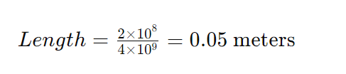
So, the length of the quarter wave transformer required would be 0.05 meters.
FAQs
Q: What is a quarter wave transformer?
A: A quarter wave transformer is a transmission line used to match the impedance between two circuits.
Q: Why is impedance matching important?
A: Impedance matching ensures maximum power transfer between the source and load, minimizing reflections and signal loss.
Q: Can this calculator be used for other applications?
A: While primarily designed for quarter wave transformers, similar principles may apply to other impedance matching scenarios.
Conclusion
The quarter wave transformer calculator is a valuable tool for engineers and enthusiasts working with transmission lines. By understanding its usage, formula, and application, users can effectively design and analyze transmission systems with optimized impedance matching.